ArdCore - An Arduino-based Compute Device for Modular Synthesizers

Please note: The Ardcore project is no longer being actively developed. SnazzyFX may still have Eurorack modules available, and others have created 'clone' boards (with my blessing). But Ardcore boards are no longer available from me or 20 Objects.
For more information about getting started: link
For more information about the available Arduino sketches: link
For more information about building the ArdCore: link
For more information about the expanders: link
The schematics for the original ArdCore board is available from this link. It was created using an older version of the ExpressPCB software, possibly still available from their site.
Overview
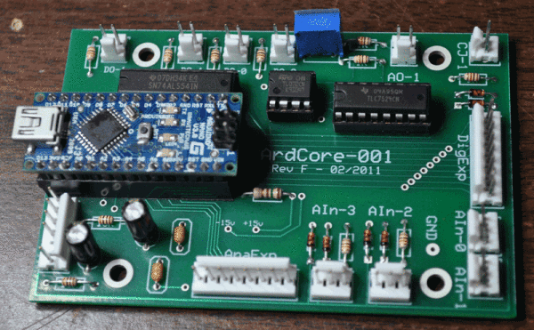
As part of my Masters Degree at University of Denver, I (Darwin) have developed a specification for the use of the Arduino microcontroller as a generalized compute device for modular synths. What does that mouthful of words represent? It means that I've developed a module that can perform a multitude of different functions, controlled by Arduino sketches that you (or I) can create.
The purpose of this device is three-fold:
- To allow programming-savvy artists to pursue synthesis options that aren't currently available (either because they are too difficult or too idiosyncratic).
- To allow for temporary-use function that are not often needed (and hence not worth the expense or space) but may be important for a specific composition.
- To provide a simple platform for functions that are much easier to accomplish in the digital domain than in the analog domain.
This page, and our site, will provide a number of different things for interested modular users:
1. A specification for the use of the Arduino in a modular environment.
2. Examples of sketches that can be used for Arduino-based modules that follow the specification.
3. Examples of boards that can use the Arduino in an embedded module.
4. Completed boards and modules (for sale) that implement this specification.
The current specification document can be viewed from this PDF file (which will be constantly updated as new information is made available).
Design Decisions
 In order to focus on a single platform for development, we made a few design decisions that drove the development of both the specification and the board we've created:
- We would focus on CV generation and manipulation, and limit our explorations of audio output.
- We would produce output with 8-bit resolution, and do so by the direct manipulation of digital output pins (one pin per bit).
- We would limit both input and output ranges to a 0-5 Volt range. This is the most useful range for control voltages to affect oscillators and filters, and is therefore our main targeted connection.
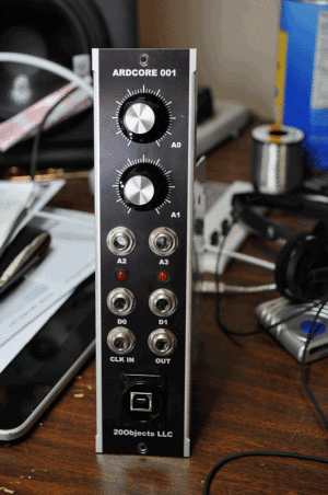
- We would fit the main unit in a single width 5U (MU) space. Additions would be made that would provide enhanced input and output expansion, but the core computational engine could be effectively used in a single MU width.
These four decisions were made for a number of reasons. Part of it is to keep the circuit (and therefore board construction for DIY'ers) very simple. It is also to simplifly the programming of Arduino sketches that would make for useful output. Finally, we want this module to be usable in a lot of different environments (performance, studio, installation), so having a minimal space footprint was very important.
Some may question the use of 8-bit output, but it is a compromise that we ended up appreciating once we saw that a) it made programming very easy, even with low-end Arduino boards, and b) the resolution was sufficient (especially if paired with a slew limiter) for every sort of output we needed. Our test results have been very positive, and the result is used in our systems every day.
NOTE: All available sketches can be downloaded from our Github location.
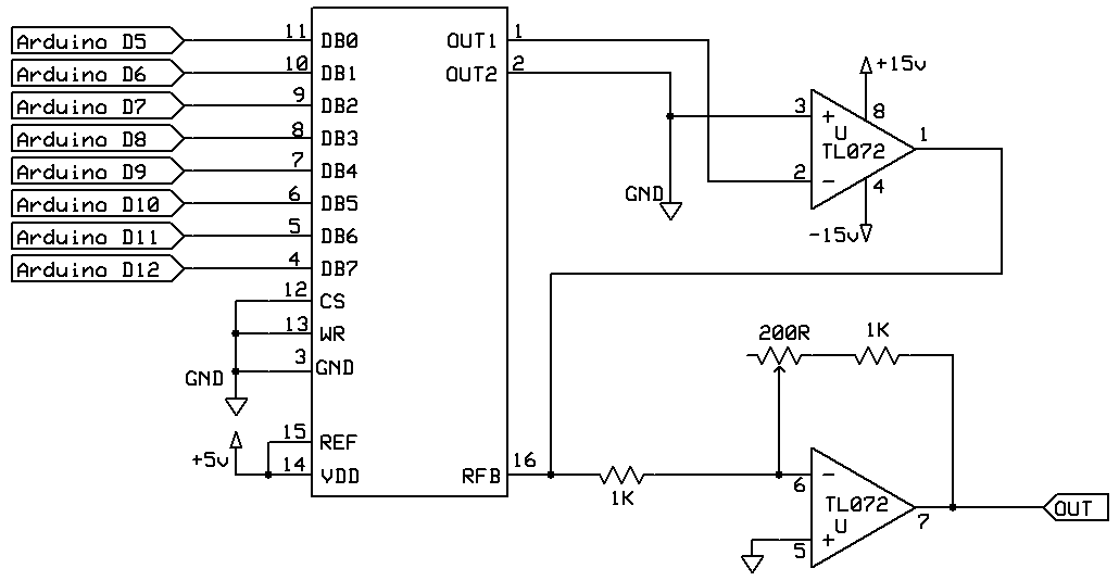
Circuit Diagram for DAC section
You can condition the inputs to the Arduino in many ways; I chose to use a 1K resistor in series to the input, and diodes that sink excess positive and negative voltage to the +5 and GND rails, respectively. However, the DAC section is the more difficult challenge.
Here is a schematic of the output section of the device. I use a TLC7524 DAC chip because it is fast, and because I happened to have access to some. You could use a DAC0800 or something else, I chose this one for convenience.
The TL072 is something I learned from studying the dotcom synthesizer boards; Roger uses TL07n chips everywhere, and in looking them over, I understand why. Nice lil' chip.

[ddg]
updated 11-24-2019

